Current Carrying Capacity is defined as "the maximum electrical current that can be continuously carried by a conductor, without causing an objectionable degradiation of electrical or mechanical properties of the product" (IPC-2152). It is easy to oversize trace dimensions: just make it wide and thick (cf. White Paper Nr.2), (Blog). To master the constrains from area, environmental condititon and probably time is far beyond guessings and is the realm of detailled TRM simulations.
Electric current is creating heat ...
It is easy to calculate the electric resistance of a trace and to multiply by I². But you wouldn't know how to convert power to temperature. That depends on heat transfer within the PCB and loss of heat to the ambient. The equilibrium between heat generation and heat loss is represented by the temperature value.
... and what will be temperature?
This is answered by a 3-D simulation with TRM. The images below demonstrate that even the most simple trace geometry can show a variety of temperatures depending on the board properties and layout. Old IPC-2221 is assuming a bi-layer board with a bottom copper cladding (undocumented). New IPC-2152 uses a worst case scenario on a single layer board.
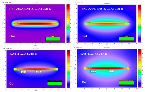
Top left: one trace on a single layer board: Bottom left: single layer but copper flooding around the trace with gap. Top right: one trace with copper cladding on bottom; Bottom right: bi-layer with top layer copper flooding. All calculations done with 11 Ampere.