The thermal resistance "Junction-Ambient" ΘJA or RΘJA links a temperature node inside the silicon die (Junction) with the surrounding air (Ambient). "Ambient" includes everything around the component, from the pad to the air - i.e. especially the special topology of the PCB. Therefore RΘJA cannot be used to predict the temperature for a specific board. Here are some screenshots from Don't believe the data sheets. Design007 Magazine (September 2020).They show that the heat spreading on a real PCB is not perfect and that it was certainly different on the test PCB of the data sheet.
- This Arduino board is 2-layer. The parallel running tracks can improve and impede the heat spreading.
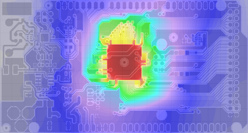
- Even with multilayer boards with solid inner layers, the layout can dominate the heat spreading. In this evaluation board we see that the thermal vias are in fact useless, because they are just as warm as the component, so no heat is removed.
