TRM3.10 is available.
Highlights:
Interface Pulsonix 14 <-> TRM
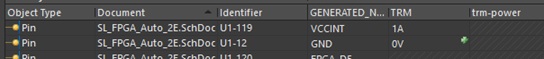
- PSX: Define attributes as watts, amps, volts (optional)
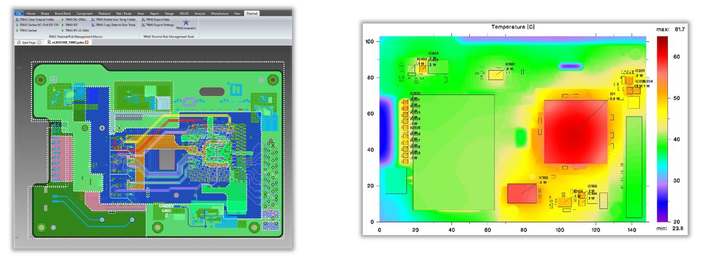
- PSX: Automatic transfer of all layers, prepregs, drill holes (through, blind, buried), pins (netlist), components and attributes to TRM
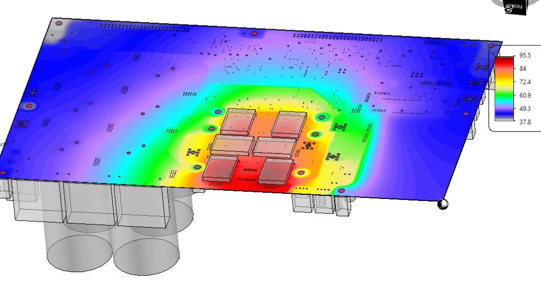
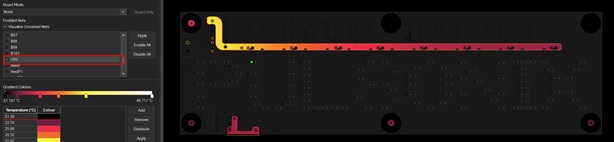
- TRM: Import (wizard) automatically creates a board model ready for calculation
- PSX: Import of results for visualisation in design (optional)
Altium Interface
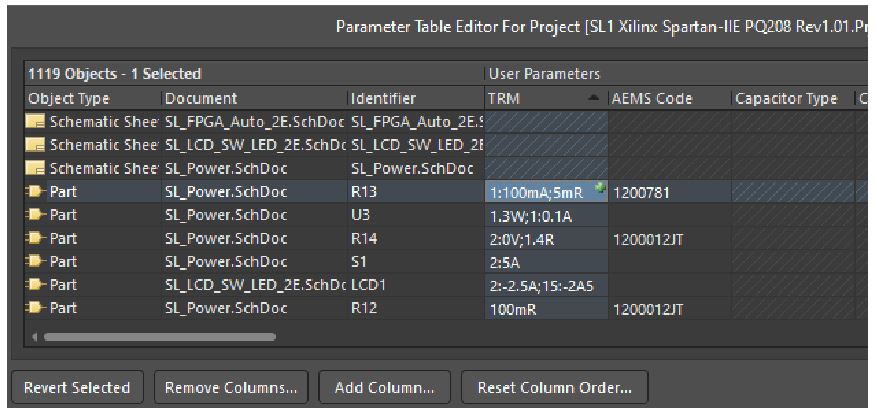
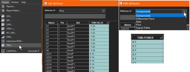
- Electric assignment to pins now also available in Parameter Manager
Zuken
- eCADSTAR interface. Simplification of buttons and installation
- CR-5000/CR-8000. Netlist
Circuit simulation
- Resumption from TRM2
- Define currents in sections of time or phase with MS-Excel and calculate the load integral, e.g. for one period
Calculation
- Simpler import of non-rectangular board contour and cutouts
- Transient ambient temperature
Ask for a trial period: Request Form