More data! Now netlists with their pads/pins can also be imported from other CAD systems, e.g. from Cadence (Allegro, Orcad), Mentor (Pads, Expedition), Zuken (Cadstar, CR8000), Eagle, Pulsonix, KiCad etc. You only have to export the IPC-D-356 file. This makes it much easier to investigate the current carrying capacity of high current applications.
- Import ipc file: creates a table with all the nets and pads found.
- Add Ampere values: either manually or via a .csv file, which could also come from an xls calculation.
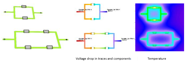
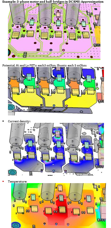
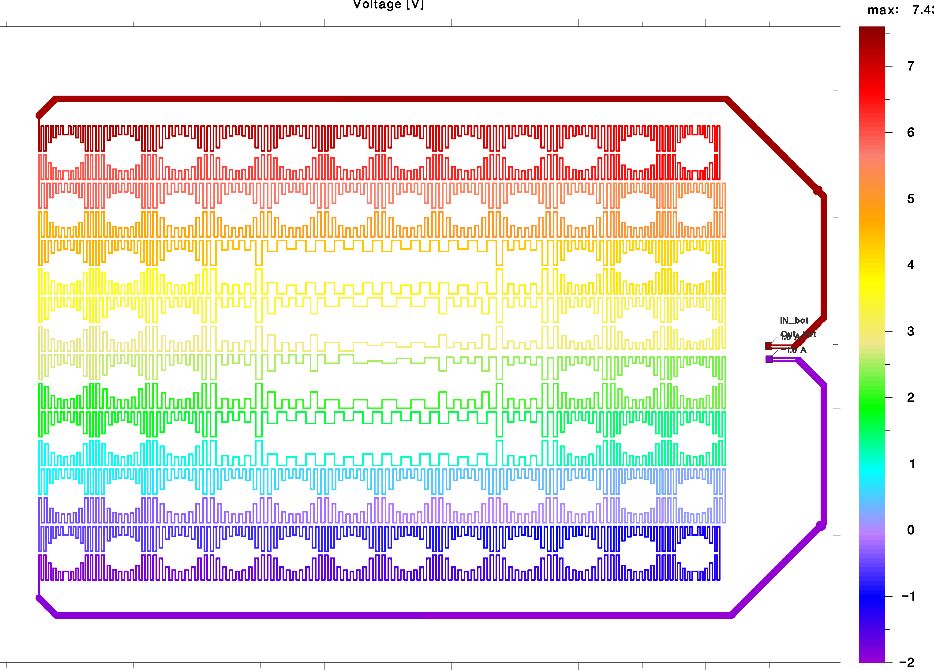
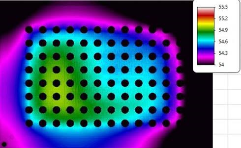
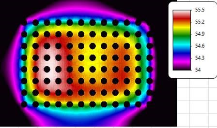
- Calculate how the current heats the traces. Of course also transient.
Altium users will still prefer the script. But there have been small updates as well.
More color! The imported Gerber files are no longer just black and white plots, making it difficult to distinguish layers, but are now displayed in color. This results in a fantastic depth effect in the 3D representation, which helps enormously to control the inputs and to understand the results better and to communicate them to colleagues.
Convince yourself: There is a collection of new videos on YouTube